BAY 01 — ISO 17025 DYNAMIC RUNOUT VERIFICATION
RADIAL BALANCE.
ABSOLUTE CONTROL.TO ±0.01 MM.
Where the chassis meets the road, every micron matters. Road force analysis, laser alignment and wheel calibration. Measured. Not guessed.
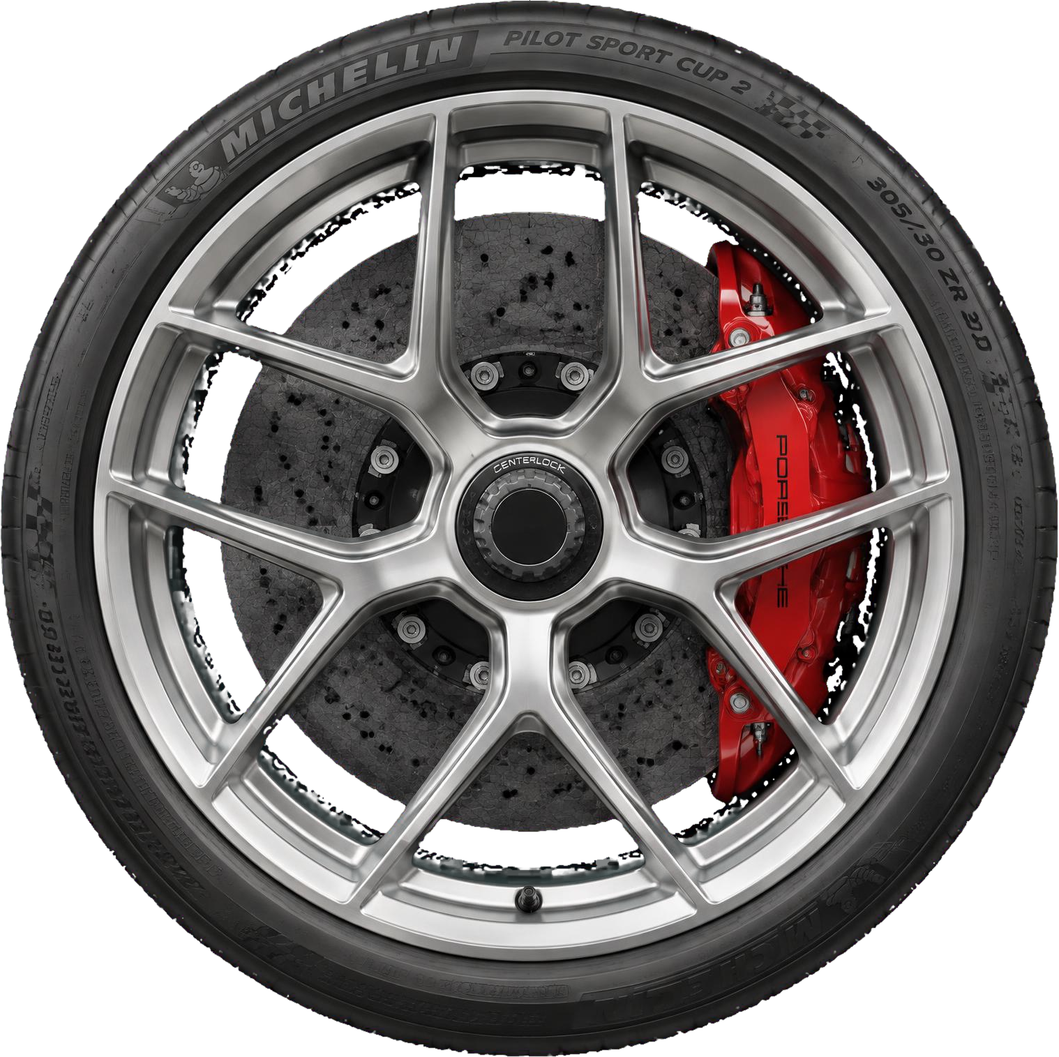
ELIMINATING THE
1ST ORDER
ROTATIONAL HARMONIC.
Static balance is only half the equation. Loaded roller analysis isolates radial force variation to identify the source of high-speed chassis vibration.
REFERENCE TARGET / LOAD-CORRECTED ASSEMBLY
ILLUSTRATIVE RESPONSE · NOT A LIVE SENSOR FEED
MODEL: Σ Aₙ SIN(NωT + φₙ) · IDENTICAL SCALE
GEOMETRY.
WITHOUT
COMPROMISE.
Four axes. One contact patch. Alignment referenced to the chassis datum, not the steering wheel.
- CAMBER ANGLE
- Wheel inclination relative to the vertical axis.
- TOE-IN RATIO
- Symmetrical convergence across the front axle.
- CASTER AXIS
- Steering-axis inclination in the longitudinal plane.
- SCRUB RADIUS
- Contact patch offset from the steering-axis ground intercept.
THE TOLERANCE
IS THE STANDARD.
Twelve reference parameters. No ambiguity between a measurement and a limit.
ILLUSTRATIVE WORKSHOP REFERENCES. VEHICLE AND EQUIPMENT MANUFACTURER LIMITS ALWAYS TAKE PRECEDENCE.
HARMONIC RUNOUT INSPECTION
THE SETUP FOLLOWS
THE APPLICATION.
A circuit apex and a long-distance grand tour demand different geometry. Select a reference profile.
−2.15° ±0.02°
High lateral load / dry circuit
CUP 2 R
Track-focused competition compound
< 15 N
Road force reference / per assembly
REFERENCE PROFILES ONLY / FINAL SETTINGS REQUIRE VEHICLE-SPECIFIC MEASUREMENT.
THE MACHINE ON THE ROAD
TELLS THE TRUTH.
BAY RESERVATION / VEHICLE-SPECIFIC INSPECTION
ALL READINGS SHOWN ARE DEMONSTRATION REFERENCES, NOT COMPLETED TEST RESULTS.